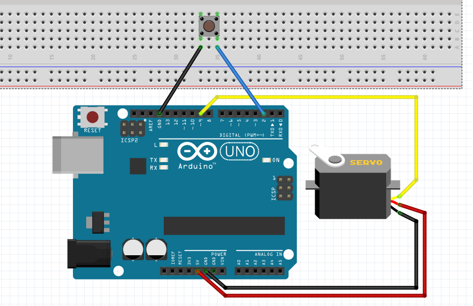

we start the function by attaching the servo object created to pin D8 of the microcontroller, after which we center the servo, turning it to zero degrees. Connect the yellow wire which is control wire to pwm pin 9 of Arduino. With this done, we proceed to the void setup() function. A servo motor will have mainly there wires, one is for positive voltage another is for ground and last one is for position setting. Servo motors are available at different shapes and sizes. Next, we create an object of the library, to be used as a reference for controlling our servo motor throughout the code. Circuit Diagram What is a Servo Motor Before going into detail, first we should know about Servo Motors.
#SERVO MOTOR ARDUINO CODE CODE#
We start the code for the project by including the libraries that we will use which in this case is the servo.h library.
#SERVO MOTOR ARDUINO CODE DOWNLOAD#
The library comes pre-installed in the Arduino IDE removing the need for us to download and install. The library makes it easy to turn the servo at different angles using a single command. The code for this project is quite easy thanks to the very comprehensive and concise servo.h library developed by the Arduino team to facilitate the use of servo motors in Arduino projects. With the connection all done, we can now proceed to write the code for the project. No you dont have to change any time delay in order to get it rotating by 90 degrees, delay would just change the speed of rotation of the servo. Servo directions are sent from the microcontroller to the servo motor as PWM pulses.

The signal pin was connected to the digital pin 8 of the Arduino because it is a PWM pin. Schematicsįor emphasis, the connection is further described below. The Signal pin is the one used to feed the control signal from the microcontroller to the servo, to get the servo rotate to a particular angle.Ĭonnect the Servo to the Arduino as shown in the schematics below. Maximum number of servo motors Arduino UNO can handle is up to 12 with Arduino library for servo, and maximum of 48 servos can be connected with boards like. Servo motors generally have three pins/wires, this includes the VCC, GND, and the Signal pin. The schematics for this project is quite simple as we will be connecting just the servo motor to the Arduino. The following components are required to build this project:Įach of these components can be bought via the link attached to them.

Since we will be using just one servo in this tutorial its fine to power it with an Arduino. Servo’s have high current requirement so when using more than one servo motor with the Arduino, it is important to connect their power connections to an external power supply as the Arduino may not be able to source the current needed for the servo. For this tutorial, we will be using the popular SG90 servo motor and our goal will be to rotate the servo motor from one end to the other.


 0 kommentar(er)
